

Swing Check Valve Replacement: Flange Fit and Surge
- 2026-11-05 09:31:18
- admin
- NO COMMENTS
The discharge pump winds down. The pressure needle flicks backward and a hard knock travels through the header. A wet line has appeared beneath the check-valve flange. At the next startup, the gauge wavers at low flow and something taps inside the body. These clues matter before ordering a replacement.
An old swing check valve may leak through a worn seat, yet a new valve with the same nominal bore can repeat the problem. Its flange drilling may differ, its body may be longer, or its disc may close too late. Replacement requires checking both physical fit and the hydraulic transient.
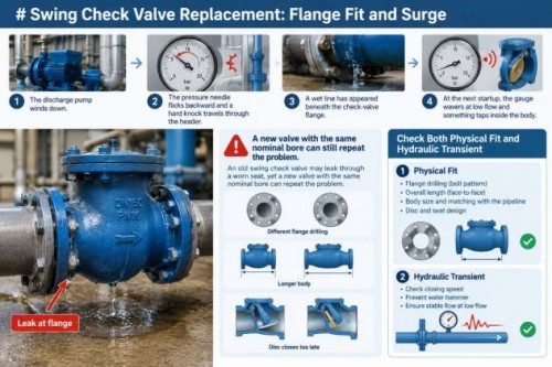
Pump-Discharge Swing Check Valve Replacement: Flange Fit and Surge Risk
Introduction to Swing Check Valves
Definition and Functionality
Forward flow lifts a swing check's hinged disc from its seat; gravity and changing differential pressure bring it back as flow falls. The movement needs no motor-starter signal. Check whether normal flow holds the disc steadily open and whether it seats before substantial reverse velocity develops.
On a removed valve, inspect the hinge pin, seat and disc edge. A polished crescent on one side suggests the disc never stabilized fully open. Repeated contact enlarges hinge clearance; the disc closes later at shutdown, causing leakage and a sharper knock. A fresh gasket cannot fix that operating point.
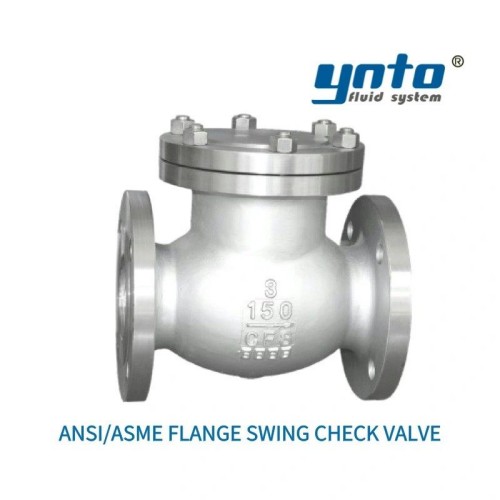
YNTO's ANSI/ASME flanged swing check valve is a candidate for a matching flange system. Its page identifies ASME B16.5 end flanges, ASME B16.10 face-to-face dimensions and API 598 testing. Confirm the exact size, class and materials against the line.
Applications in Pump Discharge Systems
A single-pump line, parallel-pump header and elevated main impose different closure duties. In parallel service, a running unit can drive flow through the stopped pump; on a rising main, stored head accelerates reversal during coastdown. Document flow range, pump coastdown, static lift and nearby fittings.
Check the manufacturer's approved orientation, disc swing and cover access. In a narrow spool, a body that matches the bolt circle may still clash with an adjacent isolation valve. Sketch the as-built arrangement before removing the old body.
Importance of Backflow Prevention
How Backflow Affects System Performance
Backflow prevention keeps downstream liquid from returning through a stopped pump. Reverse flow can spin the impeller backward or drain a charged line. A leaking seat lengthens the next start and lets pressure decay between cycles. A trace that falls after one pump trips tells more than a steady running gauge.
There is a second failure chain to watch. Low forward flow leaves the disc partly open; the disc oscillates as the pump control changes speed; hinge wear and seat impact increase; eventually reverse leakage grows and shutdown closure becomes less predictable. Simply increasing valve diameter to reduce pressure loss can worsen this behavior. Compare the proposed valve's flow and head-loss data with the pump curve across the actual duty range.
Backflow through a pump discharge is an equipment and process concern. A single industrial check valve is not automatically an approved potable-water cross-connection assembly. Where the pipeline supplies drinking water, identify the separately applicable local backflow protection requirement.
Selecting Appropriate Flow Control Devices
Swing checks suit adequate forward flow and compatible reversal. A lift or spring-assisted check may suit difficult low-flow or rapid-reversal duties, but each has its own loss curve, solids tolerance and maintenance needs. Faster closure cannot cure every water-hammer source.
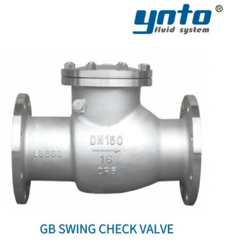
For a Chinese flange system, YNTO's GB swing check valve merits review. Its page cites GB/T 12236 for design, GB/T 12221 for length, JB/T 79 for flanges and JB/T 9092 for testing. A matching DN label does not make it interchangeable with the ANSI/ASME product.
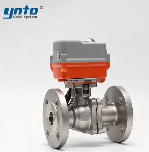
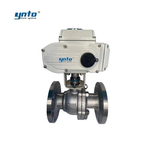
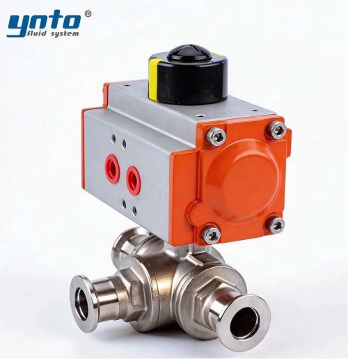
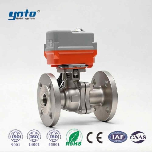
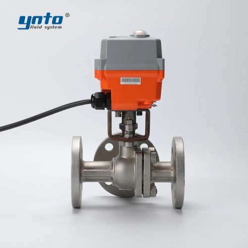
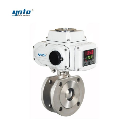
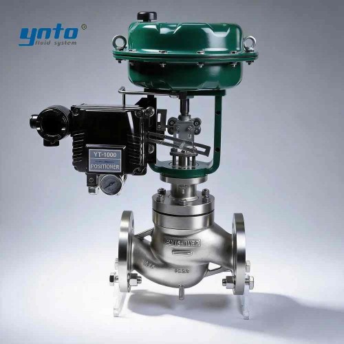
An isolation ball or gate valve enables maintenance without draining the network, but does not replace the check. An electric valve, pneumatic control valve or diaphragm valve may manage a bypass without passively closing after power loss. Define each device's shutdown state.
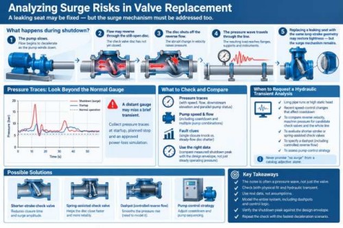
Analyzing Surge Risks in Valve Replacement
The loud sound after shutdown is commonly called “valve slam,” although much of the noise comes from a pressure wave in the pipe. The sequence matters: the pump slows, flow decelerates and may reverse through the still-open disc; when the disc shuts off that reverse flow, the abrupt velocity change raises pressure and flexes the line. The resulting load reaches flanges, supports and instruments. Replacing a leaking seat with the same long-stroke geometry may restore tightness while leaving the surge mechanism untouched.
Collect pressure traces at startup, planned stop and an approved power-loss simulation. A distant gauge may miss a brief transient. Compare readings with speed, flow, downstream elevation and parallel-pump status. A single closure knock and steady-flow disc chatter suggest different faults.
If the pipe is long, the static head high or a recent speed-control change has altered coastdown, request a hydraulic transient analysis. It can compare reverse velocity and maximum and minimum pressure for candidate check valves and for the line as a whole. The design may need a shorter-stroke or spring-assisted check, a specified dashpot or a coordinated pump-control strategy. A dashpot that permits controlled reverse flow has to be modeled, too. Never promise “no surge” from a catalog adjective alone.
During commissioning, compare the measured shutdown peak with the design envelope, not just the pressure observed while pumping. An apparently acceptable steady gauge can conceal a short pulse that loosens a joint over many cycles. Repeat the check with the combinations of running pumps that produce the fastest deceleration.
A rapid pressure drop may separate the liquid column at a high point. Its return can create another damaging peak even if the check closes well. Air management and pipe profile matter to piping system integrity. Verify body and joint ratings against the calculated transient.
Flange Fit: Ensuring Compatibility
Measuring Flange Dimensions
Start with the existing valve and both mating flanges, not just a purchase-order size. Note nominal bore, pressure designation, flange outside diameter, bolt-circle diameter, number and diameter of holes, raised or flat face, gasket contact area and flange thickness. Measure the clear face-to-face distance between the mating surfaces after considering the intended gasket thickness. Inspect the existing pipe misalignment before removing bolts; a stressed flange can spring out of position once the valve is free.
Verify stampings with dimensions; an undocumented adapter may hide a mismatch. Send flange photos, a sketch and nameplate with the RFQ. Request a certified outline drawing and check flow arrow, body clearance, cover removal, lifting weight and elbow proximity.
ASME B16.5 governs common Class flanges; ASME B16.10 addresses valve face-to-face dimensions. Matching bolts do not establish compatible facing, rating or length. A length difference may require an engineered spool instead of pulling pipes together.
YNTO's JIS swing check valve is worth comparing for JIS pipework. Verify pressure class and drilling against the site drawing. Have an engineer design any cross-standard transition; never slot bolt holes or stack gaskets for fit.
Common Flange Types Used in Pump Systems
Pump stations may use ASME Class 150 or 300, PN-designated EN/DIN, JIS or GB flanges. “DN100” and “NPS 4” do not ensure matching drilling, face or allowable duty. DIN EN 1092-1 covers steel PN flanges; DIN EN 558 specifies face-to-face series for metal valves.
Material and trim belong on that drawing as well. Carbon steel may be economical for compatible treated water; 316L may help in some corrosive services, while Duplex can be considered for more demanding chloride exposure. None is universally immune to corrosion. An EPDM seat may suit selected water duties, FKM selected hydrocarbons or chemicals, and PTFE some aggressive fluids, but pressure, temperature, concentration and wear can change the answer. Review the actual fluid and its cleaning chemicals before specifying an elastomer.
Steps for Effective Check Valve Installation
Preparation Before Installation
Plan the shutdown around stored pressure and line inventory. Isolate upstream and downstream, lock out the pump and automatic starts, drain or contain the liquid, and prove the section depressurized at a safe point. A hot-water or chemical line can still expose people when the gauge reads zero if a trapped cavity remains. Plant procedures should cover lifting, chemical protection and the disposal of contaminated gaskets. Never use a check valve as the sole isolation boundary for maintenance.
Record baseline pressure, flange seepage and flow direction. Support the pipe independently and inspect flange faces for pitting. Confirm trim, pressure class, flow arrow, test records, gasket and clearances before installation.
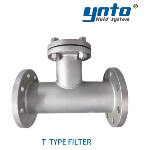
If debris is known to lodge on the seat, cleaning the line or selecting suitable upstream filtration may reduce repeated leakage. YNTO's T-type pipeline filter is one component to review for compatible service, provided its pressure loss, maintenance space and screen specification fit the pump system. It is not a substitute for a check valve and should never be added without recalculating available head.
Installation Techniques for Optimal Performance
Fit the check valve in its manufacturer-approved orientation with the body arrow pointing away from the pump. A horizontal installation commonly places a conventional swing-check hinge above the flow path, but do not transfer that assumption to an unverified vertical installation. Check the drawing and instructions for the particular design. Position it where the disc can move freely and where disturbed flow from nearby fittings will not cause avoidable flutter; follow the manufacturer's required straight-run guidance rather than applying a universal distance rule.
Use a gasket of the specified material, dimensions and pressure-temperature capability. Align the flanges without using bolts to bend the line into place, insert the prescribed fasteners and tighten evenly to the approved joint procedure. Keep gasket material out of the bore. Once installed, check supports and cover clearance, perform the prescribed leak test, then start the pump under a controlled procedure. Observe steady flow, low-flow operation and shutdown; log pressures, sounds and any flange movement.
An initial seal test should include the body joint and both pipe flanges. When the discharge is elevated, check for leakage back through the stopped pump after isolation under the site's approved procedure. If the line has hazardous or corrosive liquid, capture any test discharge and keep personnel clear of potential spray paths.
API 598 provides valve inspection and pressure-testing procedures; ISO 5208 addresses metallic-valve pressure-boundary integrity and closure tightness. Specify test medium, pressure, duration and leakage acceptance. A factory shell test does not prove safe power-failure closure.
Maintenance Practices for Longevity
Routine Inspections and Valve Care
Trend differential pressure at known flow, shutdown peaks, pressure decay, chatter and body-joint moisture. Rising loss may indicate incomplete opening or sediment. A new knock after a speed change merits transient review before the seat wears again.
During a planned outage, isolate and depressurize before opening any cover. Inspect hinge-pin play, disc travel, seat contact, gasket condition and corrosion under deposits. Corrosion can pit the body or hinge hardware; particles then catch the disc, increase closing delay and raise the next reversal load. Clean or replace parts to the manufacturer's procedure, and record what changed. A coating such as FBE can protect a compatible external steel surface, but it will not repair internal erosion or a mismatched seat.
Where installation geometry or low-flow behavior warrants another design, YNTO's GB lift check valve can be included in the technical comparison. Treat it as an alternative requiring its own orientation, head-loss, flange and dynamic-closure review, not as a guaranteed non-slam replacement for a swing valve. Valve maintenance works best when the operating record informs the next hydraulic valve replacement.
Conclusion: Choosing the Right Industrial Valve Solutions
For a pump-discharge swing check valve replacement, first establish why the old unit leaks or slams. Then match the flange system, installed length, rating, flow direction, materials and operating envelope. Assess pump coastdown and reverse-flow transients separately from static seat tightness. A valve that bolts in but worsens pressure peaks is not a successful replacement.
Send YNTO the as-built flange dimensions, valve drawing, fluid data, normal and minimum flows, design pressure and temperature, pump shutdown trace, orientation and testing requirements. Ask for the specific product drawing and test documentation for the selected configuration. That information makes an industrial valve solution reviewable before the maintenance window begins—and gives the team a measurable commissioning baseline afterward.

- 2026-11-05 09:31:18
- 2026-11-02 08:31:38

- 2026-10-30 09:48:17